
Key Takeaways
- A can filling and seaming machine interface matrix should identify where each connection ends, the conditions it must meet, who supplies and installs each side, and how both parties will ver…
- The matrix below is a planning template. Connection dimensions, utility limits and control responses come from the approved configuration and project drawings. It does not specify universal…
- Mark the machine, existing equipment and third-party equipment on the same layout revision. Give each transfer point, pipe connection and control interface an ID. Identify the direction of c…
Author: Mengdi · Technical reviewer: Hanyong · Content updated: 23 September 2026
A can filling and seaming machine interface matrix should identify where each connection ends, the conditions it must meet, who supplies and installs each side, and how both parties will verify it. Use one controlled record for each physical connection or exchanged signal. This turns a broad requirement such as “connect to the existing conveyor” into a checkable project agreement.
The matrix below is a planning template. Connection dimensions, utility limits and control responses come from the approved configuration and project drawings. It does not specify universal pressures, flows or electrical ratings.
Start with the boundary, not a list of utilities
Mark the machine, existing equipment and third-party equipment on the same layout revision. Give each transfer point, pipe connection and control interface an ID. Identify the direction of can flow, product flow or information flow. A connection can cross several supply scopes even when the machines stand next to each other.
For every ID, name the party supplying each end, the party installing the connection and the party responsible for the joint test. “By buyer” or “by supplier” alone is too broad when a pipe, valve, cable, conveyor section or software change is supplied separately.

A practical interface matrix
Use the rows that apply to the selected configuration. Expand a row into separate IDs when its connections, owners or operating conditions differ. On a phone, scroll the table horizontally.
| Interface | Conditions to agree | Responsibility and verification |
|---|---|---|
| Empty-can infeed | Can format, transfer elevation and direction, conveyor and guide geometry, supply rate and behavior when cans are unavailable. | Identify the owner of the final upstream conveyor section and transfer parts. Check the installed transfer with the agreed can samples. |
| Filled-can discharge | Discharge elevation, receiving conveyor, product condition, downstream capacity and the response to a blocked discharge. | Assign transfer and accumulation scope. Verify agreed stop and recovery behavior with the connected equipment. |
| Product supply | Connection location and type, product conditions, required supply range, pump or tank boundary and isolation arrangements. | Assign pipework, valves and instruments individually. Record the conditions at the agreed machine connection during the agreed operating test. |
| Electrical supply | Project voltage, phases, frequency, load information, connection point and applicable installation requirements. | Name the responsible electrical contractors and equipment suppliers. Use approved drawings and qualified personnel for installation and verification. |
| Compressed air and process gases | Required medium and quality, pressure and available flow at the connection, consumption basis and relevant operating states. | Assign treatment, distribution, isolation and measurement scope. Specify which conditions are measured and where. |
| CIP, water and drainage | Installed cleaning scope, supply and return connections, drainage destination, cleaning media and approved operating conditions. | Allocate the cleaning skid, connecting pipes and return path. Separate connection checks from cleaning-effectiveness validation. |
| Optional systems | Steam injection, nitrogen dosing or other selected equipment, only where included in the agreed configuration. | State the third-party boundary, utility demand, control coordination and test owner. An option on a product page is not automatic inclusion. |
| Controls and information | Signal meaning and direction, interface method, permissions, operating modes, loss-of-communication response and restart conditions. | Name the owner of each controller and of the interface software. Agree a joint test record before commissioning. |
Write utility conditions at the agreed connection point
For a utility entry, record its unit, measurement location, operating state and acceptance source. Distinguish a supply figure stated for the plant from a condition verified at the machine connection. State whether a flow value describes average demand or a peak duty and, for gases, the reference conditions used for the volume.
Utility monitoring can involve flow, temperature and pressure, as described in Endress+Hauser’s utility instrumentation overview. Select the measurements for the actual duty. This does not establish the required utility values for a particular Weichi model.
Agree signal meaning as well as the connection
A matching cable or network connection does not define what “ready,” “run,” “stop” or “fault” means to the adjoining machine. Record the signal sender, receiver, meaning, applicable mode and expected response. Include the agreed handling of unavailable upstream supply, blocked downstream flow and communication loss. Detailed response logic belongs in the approved controls document.
The OPC Foundation’s PackML overview explains standardized machine modes, states and tags for integration. Use an agreed interface standard where the project supports it; a PLC brand alone does not establish PackML or OPC UA capability. Safety-related functions require their own approved design and validation and must not be assumed to follow from ordinary production signals.
Keep options separate from standard scope
Weichi’s premium still beverage filler-seamer product page lists filling-valve CIP and seamer steam injection under optional upgrades and describes compatibility with third-party liquid nitrogen dosing. These entries identify subjects for an application review. The order specification must establish which systems are installed and who supplies their connections and controls.

Close each interface with a traceable record
Before fabrication, confirm the layout and interface revisions. Before installation, check that the supplied ends and site provisions match them. During testing, record the actual conditions, participants, result and any deviation. If a connection or control response changes, update the affected drawing, matrix row and test record together.
A factory test may use a temporary supply or simulated neighboring machine. Record that limitation and carry the actual site connection into the SAT plan. Use the FAT and SAT checklist to define the wider acceptance scope.
Interface ID and location:
Layout / drawing revision:
From equipment / to equipment:
Connection and operating conditions:
Supply owner for each side:
Installation owner:
Test owner and acceptance reference:
Test conditions, date and result:
Deviation, corrective action and retest:
Approval and final revision:
Questions to settle before ordering
Does a filler-seamer monoblock include the external conveyors?
The term describes an integrated machine arrangement. The quotation and scope drawing must identify external conveyors, transfer parts, controls and installation work that are included.
Can a utility list replace the matrix?
A utility list is useful input. The matrix adds exact connection boundaries, owners, operating conditions and the evidence required to close each interface.
What should be sent for an interface review?
Send the proposed machine configuration, can and product information, current layout, neighboring equipment details and available site utilities. Mark existing equipment and third-party supply. Use the quotation information checklist for the broader application inputs, then contact Weichi to confirm the equipment and connection scope.
For rate matching and buffer calculations, see line capacity planning. This interface guide focuses on connection and responsibility records.
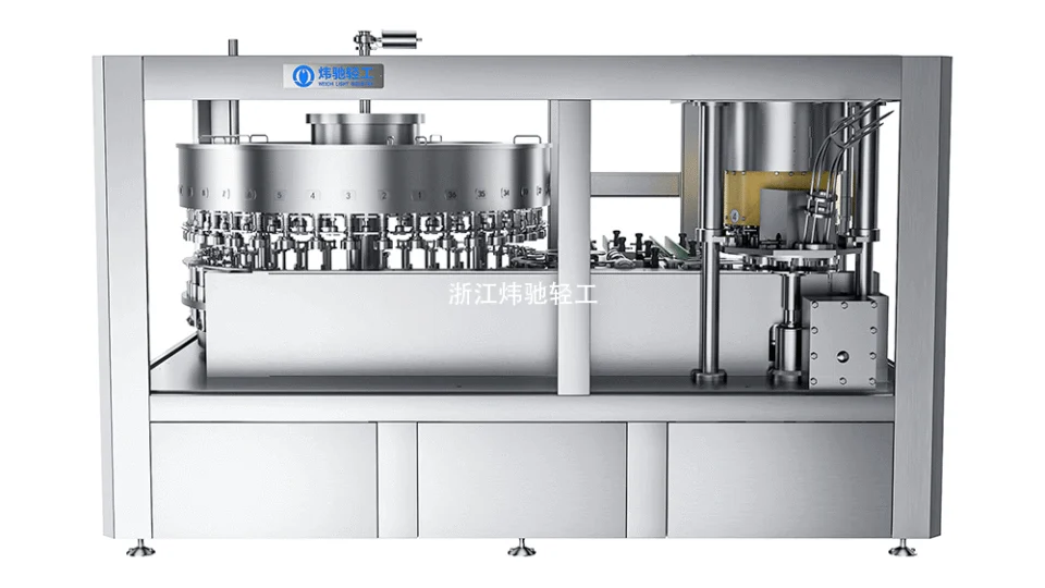
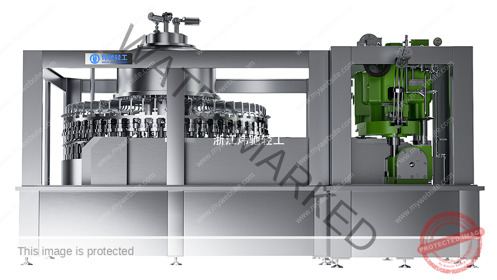
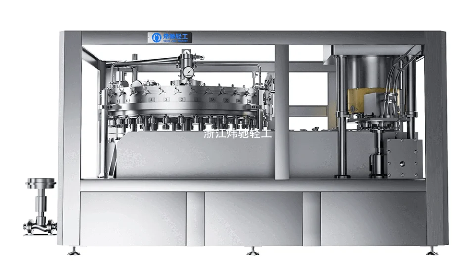
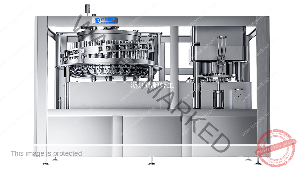
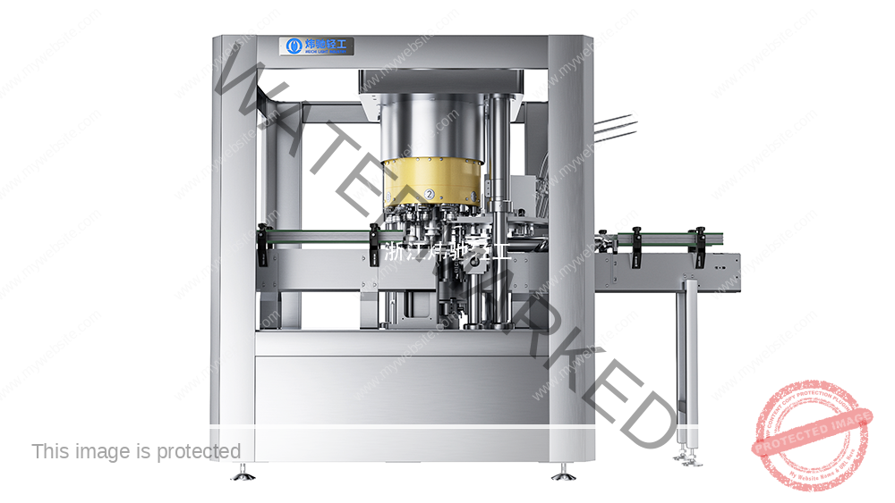
Cover: AI-generated industrial concept image, not a photograph of a supplied installation.
Technical Basis and Project Evidence
Final equipment selection and acceptance must use the project product, can and end drawings, utility conditions, line interfaces, agreed test duration, and documented FAT/SAT criteria. Can and end supplier specifications remain authoritative for double-seam limits.
- U.S. FDA: Low-Acid Canned Food Manufacturers, Part 3 — Containers and Closures
- SAMR record: GB/T 30639-2014 — Sauce filling and seaming equipment
- SAMR record: GB/T 40360-2021 — Still-beverage can filling and seaming equipment
Review equipment families See project references Submit application data