
Key Takeaways
- High-speed can seaming depends on stable mechanics, controlled tooling, consistent containers and ends, and a disciplined inspection program. Speed by itself does not demonstrate seam qualit…
- The chuck supports the end while the lifter presents the can. The first-operation roll forms the initial hooks and interlock. The second-operation roll compresses and irons the seam into its…
- The accepted result is defined by the can and end specification. External appearance can reveal obvious defects, but it cannot confirm all internal seam characteristics.
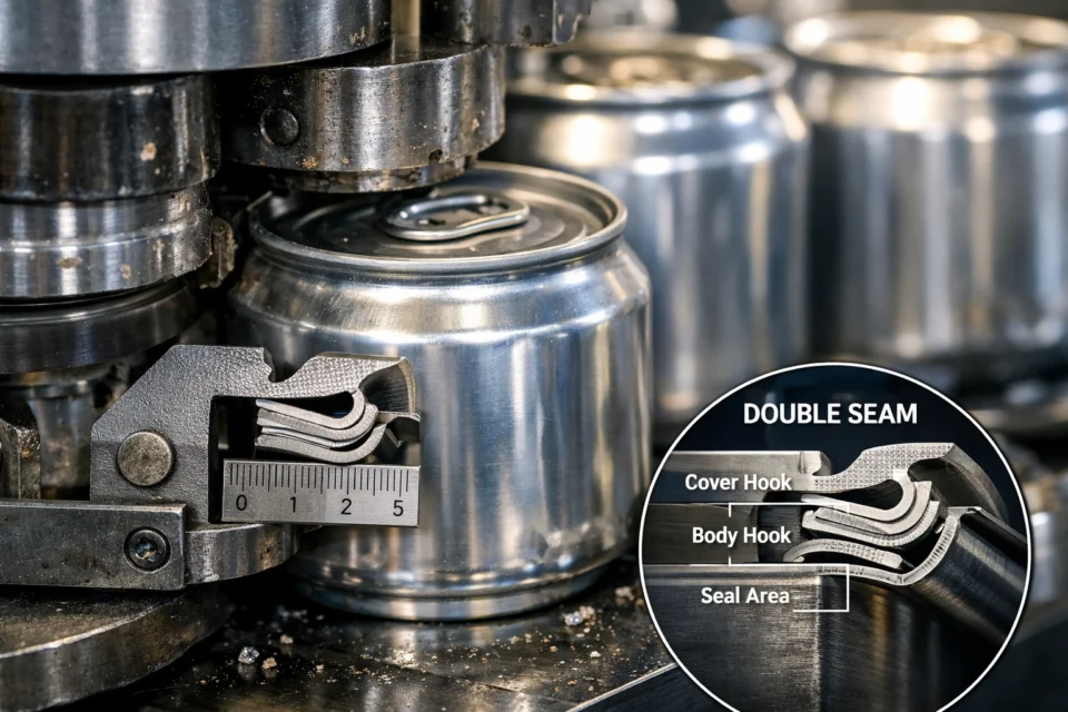
High-speed can seaming depends on stable mechanics, controlled tooling, consistent containers and ends, and a disciplined inspection program. Speed by itself does not demonstrate seam quality. The finished seam must remain within the approved specification for every seaming head and under the production conditions defined by the quality plan.
How a Rotary Can Seamer Forms the Seam
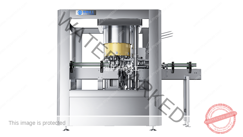
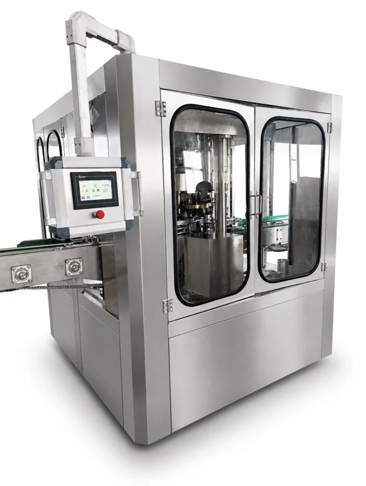
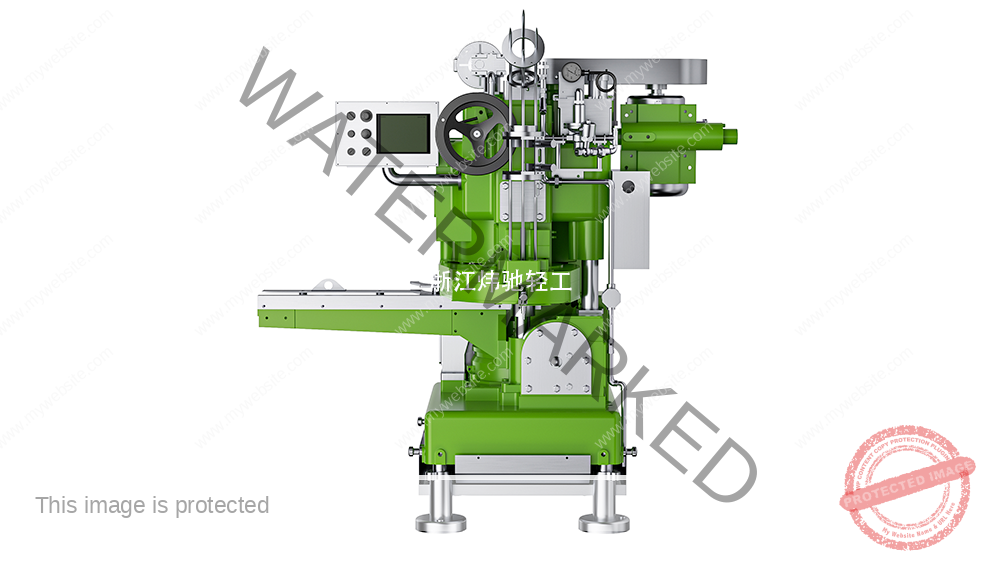
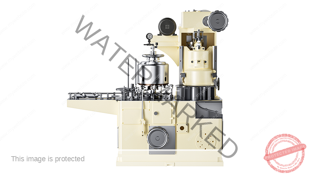
The chuck supports the end while the lifter presents the can. The first-operation roll forms the initial hooks and interlock. The second-operation roll compresses and irons the seam into its finished condition. The process must control geometry without damaging the metal, compound, can body, or end.
The accepted result is defined by the can and end specification. External appearance can reveal obvious defects, but it cannot confirm all internal seam characteristics.
Mechanical Factors That Affect Repeatability
Chuck and roll condition
Incorrect tooling, wear, damage, contamination, or runout can change hook formation and compression. Tooling identity and condition should be verified before setup changes are made.
Lifter support and alignment
The can must be centered and supported consistently. Lifter wear, unstable guidance, incorrect support, or alignment error can create variation between cycles or between seaming heads.
Cam, bearings, and drive condition
Cam profile, follower condition, bearing condition, rigidity, and drive stability influence how the rolls engage the seam. Mechanical drift may appear as gradual changes in measurements, increasing head-to-head variation, or recurring defects.
Lubrication
Lubrication affects friction, wear, follower motion, and bearing life. A centralized system is useful only when distribution is verified and the correct lubricant reaches the intended points. Oil level alone does not confirm effective lubrication.
Speed and Line Architecture
Required output should be evaluated together with the can and end range, number of seaming heads, inspection frequency, upstream and downstream equipment, accumulation, changeovers, cleaning, maintenance, and acceptable rejects. The appropriate seamer architecture should be selected from a documented line-capacity study, not from a generic speed threshold.
When the seamer is integrated with a filler, the two processes must be coordinated without allowing filling conditions, foam, lid placement, or transfer instability to compromise the seam.
Quality-Control Method
A practical program combines:
- Incoming verification of cans and ends
- External seam checks for drift and visible defects
- Teardown or cross-section inspection using the approved method
- Results recorded by seaming head or station
- Leak or integrity testing where required by the product and quality plan
- Trend review after adjustment, maintenance, tooling changes, or abnormal stops
Measurement equipment should be suitable for the method and within its calibration period. Sampling frequency and release criteria must come from the plant quality plan and the approved package specification.
Investigating Common Defects
Do not treat a visible symptom as proof of a single cause. Loose seams, wrinkles, cutover, droop, false seams, sharp edges, and local bumps may involve tooling, alignment, lifter support, component variation, contamination, end placement, or post-seam handling.
Compare results by head, component lot, operating condition, and time. Confirm the first-operation condition before changing the second operation. Make controlled changes one at a time and reinspect the complete seam rather than adjusting by appearance alone.
Testing Conditions and Acceptance
Acceptance testing should use the actual or representative can, end, tooling, product process, and line operating mode. Record:
- Machine, head, chuck, roll, and setup identification
- Can and end specifications and production lots
- Product and relevant process conditions
- Operating speed, sampling locations, and test duration
- Inspection method, acceptance limits, and measuring equipment
- Results by head and any adjustment made
Results from a different package, tooling set, product condition, or speed should not be presented as guaranteed results for the project being evaluated.
Safety Statement
This article is general engineering information. It does not replace the seamer manual, approved can and end specifications, a site risk assessment, or a qualified training program. Inspection and adjustment must be performed by trained personnel with the machine stopped and isolated as required. Restore and verify all guards and interlocks before operation.
Technical Basis and Project Evidence
Final equipment selection and acceptance must use the project product, can and end drawings, utility conditions, line interfaces, agreed test duration, and documented FAT/SAT criteria. Can and end supplier specifications remain authoritative for double-seam limits.
- U.S. FDA: Low-Acid Canned Food Manufacturers, Part 3 — Containers and Closures
- SAMR record: GB/T 30639-2014 — Sauce filling and seaming equipment
- SAMR record: GB/T 40360-2021 — Still-beverage can filling and seaming equipment
Review equipment families See project references Submit application data